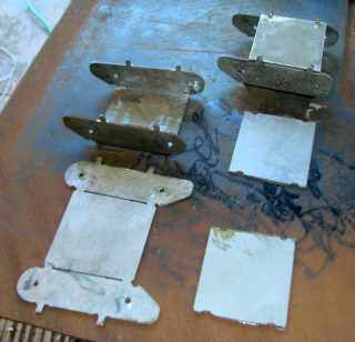


ok - here's my design - it's tapered so the front of one link fits inside the back of the next link
use 16 ga mat'l - make test cuts - kerf compensation and kerf taper matters - adjustments may be necessary to get tight fits and straight suspension
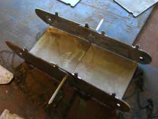
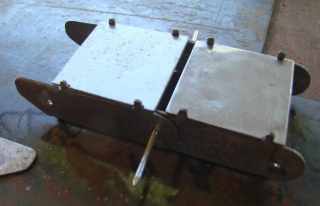
the holes are on 'Layer 1' at 1/8" diameter - pictures show nails to be tack welded inside during assembly then cut off excess after assembly (before installing covers) - you may have a better/alternate idea there
the rest is on 'Layer 2'
bend tabs are used to hold cover in place - cover could be tack-welded - whatev... -
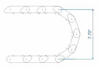
tricky part is - part width where links meet (red arrow line in 1st image - detail in 2nd image) - determines whether suspension is straight, humped or sagging - as drawn it has .015" edge taper compensation - you may have to adjust that width according to your system's taper (and kerf compensation) - in order to be exactly straight when suspended
additionally there is a flat spot (green line in 2nd image) against the cover when suspended - if there is sagging when suspended then that flat spot will pry against the cover - in which case the cover must be very securely attached - or you could change the design to remove that flat spot if sagging cannot be avoided - however the flat spot plays into limiting the flex/rotation described below - changing that part of the design may change the allowed flex/rotation between links
it is designed to flex/rotate 36 degrees between links - so when folded it should be 7.7" tall between centers (8.875" oal height) - see 3rd image
also note the bend line cuts loop back over themselves on each end - that is intentional so both ends of the bend line come out identical with no pierce point at either end of the bend line - that way both ends bend the same (and straight)
I didn't include any end links -
warning - make test cuts and adjust as necessary or it won't hang straight when suspended